


Before You Start
Before wiring the Flow3 Photo Diode, make sure the flow sensor is already installed and secured on the mainline. Use this method only when the sensor is wired directly to the controller, not on a 2-Wire path.
Watch the installation video to become familiar with the wiring layout and connection points before beginning.
What Comes in the Box
- Photo diode power supply
- Shielded two-wire cable (supplies signal to the flow sensor)
- Hot wire and common wire (used for the master valve)
- Additional wiring to supply power to the photo diode
Wiring Overview
- Confirm the flow sensor is securely mounted on the mainline before making any electrical connections.
- Connect the photo diode power supply to the controller using the terminals shown in the wiring diagram.
- Wire the shielded two-wire cable from the photo diode to the controller flow sensor input, keeping the shielding intact.
- Connect the hot and common wires to the appropriate controller terminals for master valve operation.
- Check that all wiring matches the diagram and that connections are secure before restoring power.
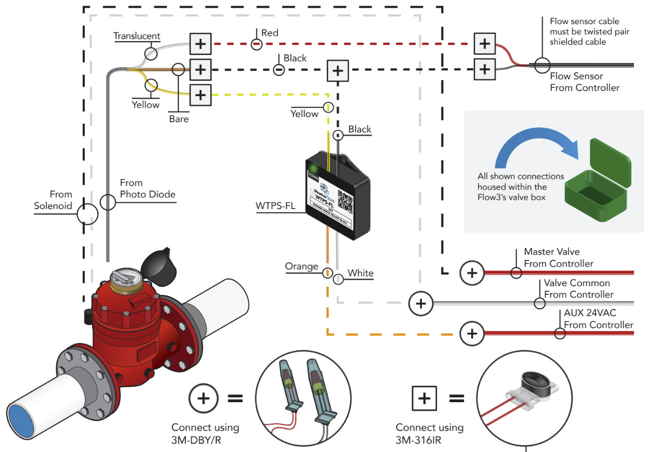
Wiring Diagram
For detailed, step-by-step wiring instructions, refer to WT_Flow3_Installation Manual starting on page 9.