


A hydraulic tree is the site’s piping infrastructure. A hydraulic tree is built by configuring the water source, the mainline, and the flow zones. Log in to Weathertrak.net to get started. 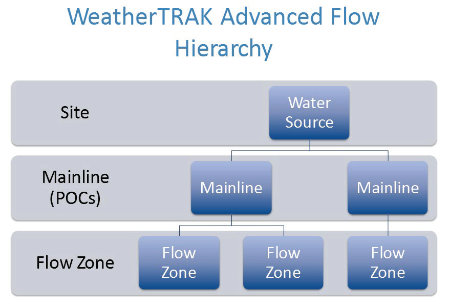
Step 1
Add the Water Source to the Site
A Water Source feeds one or more Mainlines and can be sourced from a canal or a water meter. All sites must have at least one Water Source, but there is no limit to the number of Water Sources.
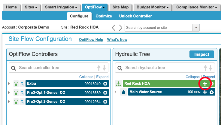
1. Click the OptiFlow tab, and then click the Configure sub-tab.
2. Select the appropriate site from the drop-down list.
3. Click the + symbol to the right of the Site name under the Hydraulic Tree.
4. The Add New Water Source screen displays. Use the drop-down tab to select Water Source.
5. In the Name field, type a descriptive name for the Water Source.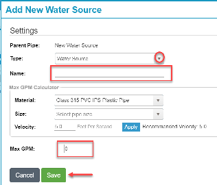
6. (Optional) Use the fields in the Max GPM Calculator box to help estimate the maximum flow rate from the water source:
a. In the Material field, click the drop-down arrow and select the pipe material from the list.
b. In the Size field, click the drop-down arrow and select a value for the pipe size.
c. In the Velocity field, type the designed water velocity (typically 5 feet per second).
d. Click Apply.
7. Perform one of these two options:
a. Enter a user-defined value in the Max GPM field or...
b. Click the Apply button to use the recommended value from the Max GPM Calculator.
8. Click Save.
Step 2
Add a Mainline to the Water Source
A Mainline represents the water delivery pipelines that supply water from the Water Source to the station valves. Only Mainlines can be assigned managed Points of Connection (POC), i.e., flow sensors, master valves (either NO or NC), and an optional pump start. Mainlines can have one or more managed POCs including looped POCs. Mainlines cannot have sub-Mainlines but can have sub-Flow Zones.
1. Click the OptiFlow tab, and then click the Configure sub-tab.
2. Select the appropriate site from the drop-down list.
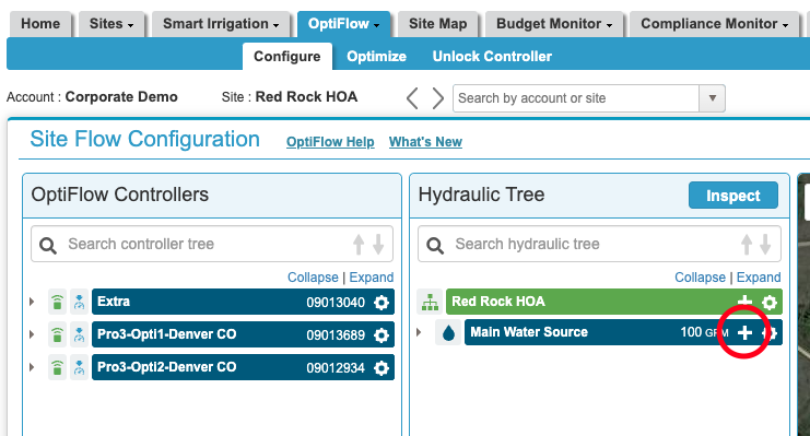
3. In the Hydraulic Tree list, find the Water Source that you want to add a Mainline to.
4. Click the + symbol next to the desired Water Source. Add New Pipe displays.
5. In the Type field, click the drop-down list and select Mainline.
6. In the Name field, type a descriptive name for the Mainline.
7. (Optional) You can use the fields in the Max GPM Calculator box to help estimate the maximum flow rate from the Mainline:
a. In the Material field, click the drop-down arrow and select the pipe material from the list.
b. In the Size field, click the drop-down arrow and select the pipe size from the list.
c. In the Velocity field, type the designed water velocity (typically 5 feet per second).
d. Click Apply.
e. In the Mainline Break Velocity, type the velocity that would indicate a break in this Mainline.
f. Click Apply.
8. Enter a user-defined value in the Max GPM field or click the Apply button to use the recommended value from the Max GPM Calculator.
9. Enter a value in the Mainline Break Threshold field or click the Apply button to use the recommended value from the Max GPM Calculator.
10. Click Next. The Flow Alerts settings display.
11. Review the default values in the Flow Alert settings, and make changes as needed.
-
Mainline Break: If the flow rate in a Mainline exceeds the mainline break threshold that was set in the Pipe Details section, the controller sends an alert, and shuts down irrigation after the amount of time indicated in the delay field.
-
No Flow: You can configure the controller to send an alert or ignore the fact that there is no detected flow in the Mainline. Set the desired no flow threshold and the amount of delay time.
-
Advanced Leak/Catastrophic Leak: If the mainline flow rate exceeds the leak detect threshold during the maintenance window, the controller will respond differently based on the type of master valve installed. Note: The controller will not perform leak detection processes while the controller is in the site irrigation window. When the controller is in the maintenance window it will perform leak detection processes.
-
For a Normally-Open master valve:
- If the leak alert occurs outside the site irrigation window, the controller will close the master valve.
- If the leak alert is active inside the site irrigation window, the controller will not close the master valve.
- If the leak alert has not been cleared, the controller will close the master valve when the site irrigation window ends. The leak alert is still active.
- The master valve will remain closed while the controller is outside the site irrigation window.
- If the leak alert has not been cleared, the controller will close the master valve when the site irrigation window ends. The leak alert is still active.
- If the leak alert occurs outside the site irrigation window, the controller will close the master valve.
-
For a Normally-Closed master valve:
- If the leak alert occurs outside the site irrigation window, the controller will keep the master valve closed.
- If a leak alert is active inside the site irrigation window, the controller will keep the master valve open for the duration of the site irrigation window. For Single-Mode controllers, the master valve will also close if no stations are running.
- If the leak alert has not been cleared, the controller will keep the master valve closed when the site irrigation window ends. The leak alert is still active.
- The master valve will remain closed while the controller is outside of the site irrigation window.
- If the leak alert has not been cleared, the controller will keep the master valve closed when the site irrigation window ends. The leak alert is still active.
- If the leak alert occurs outside the site irrigation window, the controller will keep the master valve closed.
-
For a Normally-Open master valve:
12. Assign a POC or click Save.
Step 3
Add a Point of Connection
1. In Edit Mainline Detail / Pipe Details, select the POC from the drop-down list. The list of available POCs is automatically detected based on the controllers installed.
2. In the Master Valve field, click the drop-down arrow to select the mode.
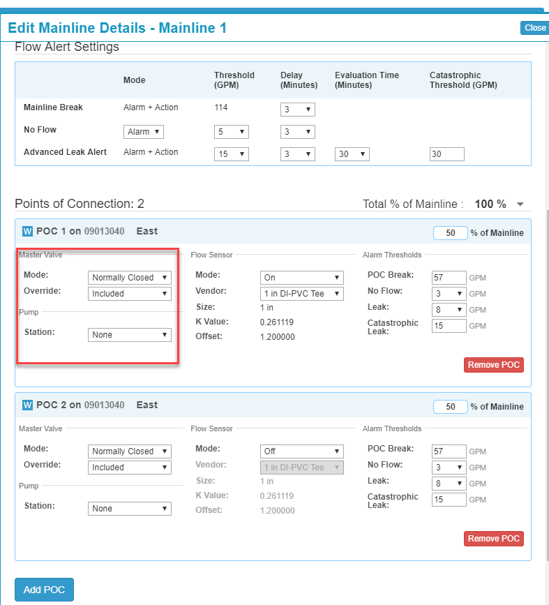
3. In the Master Valve Override field, perform one of the following actions:
- To exclude a POC from a Master Valve Override, select Excluded.
- To include a POC in a Master Valve Override, select Included.
4. Assign a POC or click Save.
5. Choose the correct flow sensor from the drop-down list.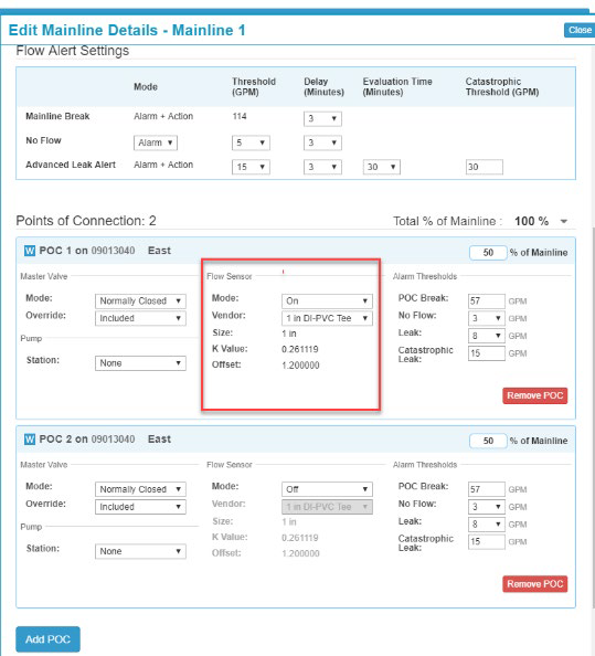
6. Click Save & Add POC.
Step 4
Set a Point of Connection Threshold
POC thresholds can be set according to what works best for your site and can be set independently of the mainline. For example, values can be set above the mainline break threshold to appropriately monitor for the actual flow you are seeing on the site. To customize the POC, No Flow Leak, and Catastrophic leak thresholds, use the drop-down tabs in the Alarm Thresholds section as pictured below.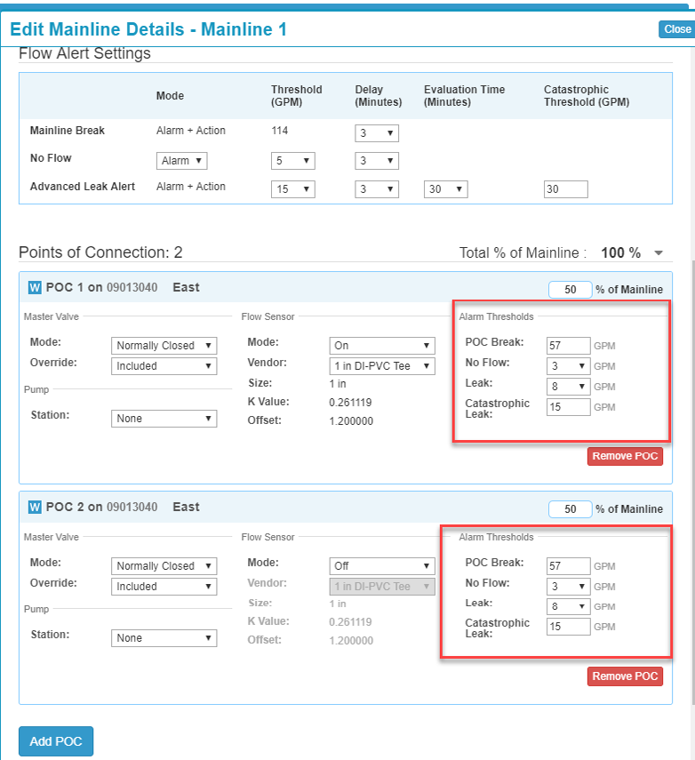
1. Set the thresholds according to the desired GPM, then click Save.
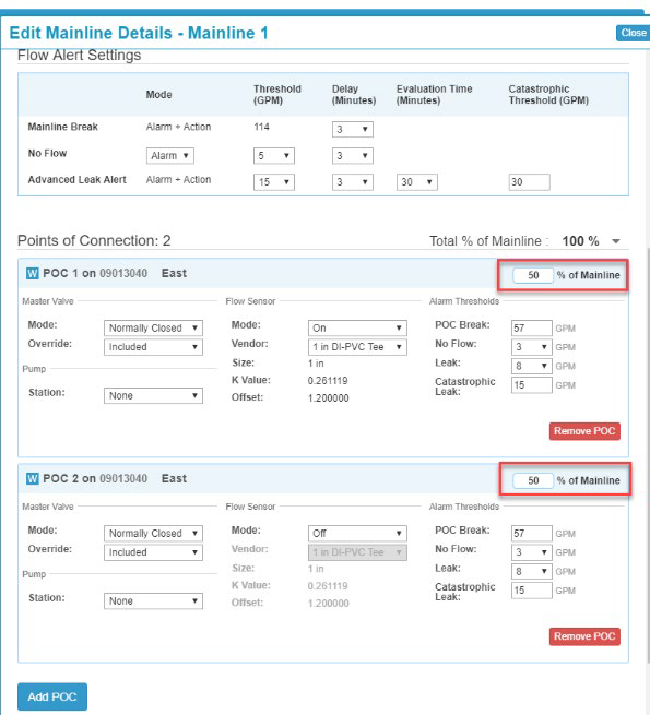
2. Set the percentage for each POC in the field as indicated below.
Step 5
Create a Flow Zone
A Flow Zone is an optional flow management tool and it is typically used to manage flow requirements on laterals, pipe size changes, or elevation changes. Flow Zones can have sub-Flow Zones. Flow Zones are used to represent complex hydraulic requirements.
1. Log in to WeatherTRAK.net.
2. Click the OptiFlow tab, and then click the Configure sub-tab.
3. Select the appropriate site from the drop-down list.
4. In the Hydraulic Tree list, find the water source or mainline that you want to add a flow zone to.
5. Click the + symbol next to the desired water source/mainline. The Add New Flow Zone pane displays on the right.
6. In the Type field, click the drop-down list, and then select Flow Zone.
7. In the Name field, type a descriptive name for the Flow Zone.
8. (Optional) Use the fields in the Max GPM Calculator box to help estimate the maximum flow rate for the Flow Zone:
a. In the Material field, click the drop-down arrow and select the pipe material from the list.
b. In the Size field, click the drop-down arrow and select the pipe size from the list.
c. In the Velocity field, type the designed water velocity (typically 5 feet per second).
d. Click Apply.
9. Type a value in the Max GPM field or click the Apply button to use the recommended value from the Max GPMCalculator.
10. Click Save.