


With Baseline’s BaseStation 3200 irrigation controller, you can use water from multiple sources to run your irrigation programs. When an irrigation system is connected to multiple water sources, the water manager usually wants to use the water from each source in a prioritized manner – typically based on the cost of the water from each source.
The BaseStation 3200 controller supports 8 water sources. If you have control points (with flow devices and master valves) associated with each water source, the controller can manage each one independently based on the priorities that you set up.
In order to draw water from separate sources based on priority, your piping structure must be designed so that your separate water sources feed into the mainline where your valves are attached and you must have a flow device such as Baseline’s BHM series hydrometer with a normally closed master valve assigned to the control point.
The BaseStation 3200 controller accommodates many ways of configuring water sources, control points, and mainlines.
You can also configure the BaseStation 3200 irrigation controller to shut down watering based on the amount of water left in a reservoir. Refer to the following articles:
Shutting Down Irrigation Based on a Water Source Empty Condition
Shutting Down Irrigation Due to Low Water in a Pond or Cistern
Step 1: Install the Flow Devices
Follow the instructions that came with your flow devices to install them in the proper locations for monitoring the flow from your water sources.
Create a diagram that shows your control points by number and the serial numbers of the associated flow devices.
DeleteStep 2: Search for and Assign the Flow Devices
The BaseStation 3200 supports up to 8 flow sensors or meters, which manage and monitor flow across a site when associated with a control point.
In addition to finding flow biCoders, this search finds two-wire flow meters with integrated master valves.
1. On the BaseStation 3200 controller, turn the dial to the Assign position.
2. Press Next or Previous to select Assign biCoders to Flow Meters, and then press Enter.
3. Press + or – to select Search in the biCoders column.
4. Press Enter to search for flow meters. The display shows the serial numbers of the devices found in the left column and the numbered ports or addresses available in the right column.
5. Press + or – to select the flow meter that you want to assign.
6. Press Next or Previous to move to the Flow Assignments column and select an available number.
7. Press Enter to assign the selected flow meter to that number.
8. When you have finished making changes, turn the dial to the RUN position.
DeleteStep 3: Search For and Assign the Master Valves
1. Turn the dial to the Assign position.
2. Press Next or Previous to select Assign biCoders to Master Valves, and then press Enter.
3. Press + or – to select Search in the biCoders column.
4. Press Enter to search for flow meters. The display shows the serial numbers of the devices found in the left column and the numbered ports or addresses available in the right column.
5. Press + or – to select the flow meter that you want to assign.
6. Press Next or Previous to move to the MV Assignments column and select an available number.
7. Press Enter to assign the selected master valve to that number.
8. When you have finished making changes, turn the dial to the RUN position.
DeleteStep 4: Assign the Master Valves and Flow Devices to the Control Points
1. Turn the dial to the Water Sources position.
2. Press Next to highlight the Assign Devices to Control Points option.
3. Press Enter. The Devices à CP screen displays.
4. In the Control Point field, press + or – to select the control point that you want to assign devices to.
5. Press Next to move to the Master Valve field, and then press + to find the device that you want to assign. 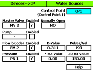
6. Press Next to move to the Enabled field. By default, the master valve is enabled. Press + or – to change the setting to disabled as needed.
7. Press Next to move to the Normally Open field, and then press + or – to toggle the value in the field between YES and NO.
8. Press Next to move to the Pump field, and then perform the following optional steps as needed:
a. Press + to find the device that you want to assign.
b. Press Next to move to the Enabled field. By default, the pump is enabled. Press + or – to change the setting to disabled as needed.
9. Press Next to move to the Flow biCoder field, and then press + to find the device that you want to assign.
10. Press Next to move to the Enabled field. By default, the flow biCoder is enabled. Press + or – to change the setting to disabled as needed.
11. Press Next to move to the K-Value field. Press + or – to enter the calibration factor for the flow device that this flow biCoder is connected to.
12. Press Next to move to the Pulses/Gal field. Press + or – to enter the calibration factor for the flow device that this flow biCoder is connected to.
13. Press Next to move to the Pressure field, and then perform the following optional steps as needed:
a. Press + to find the device that you want to assign.
b. Press Next to move to the Enabled field. By default, the pressure biCoder is enabled. Press + or – to change the setting to disabled as needed.
c. Press Next to move to the 4 ma value field. Press + or – to set the value in this field to the minimum reading when the sensor is at 4mA.
d. Press Next to move to the 20 ma value field. Press + or – to set the value in this field to the maximum reading when the sensor is at 20mA.
14. When you have finished making changes, turn the dial to the RUN position.
DeleteStep 5 – Set Up Your Control Points
When you have a control point assigned to the mainline that is the output from your reservoir, you can set up flow limits and budgets for the water flowing through this control point. The fields on the CP Settings screen are described as follows:
-
Design Flow – In this field, you can enter the specified gallons per minute (GPM) for the water running through the flow device to the connected mainline. The BaseStation 3200 uses this value to manage the number of concurrent zones so that the water is used as efficiently as possible. If you set this value to zero, you cannot use this GPM amount to control zone concurrency.
- High Flow Limit – The system uses the GPM value in this field as a critical limit. When this value is greater than zero, the system compares the limit against the measured reading from the flow device every minute. If the flow rate reading exceeds the limit for 3 or 4 minutes in a row, the system generates an alert.
If you set the Shut Down field to Y (yes), then zones (valves) assigned to this control point’s mainline will be stopped and corresponding master valves (MVs) will be shut off when the flow rate exceeds the limit.
If the flow device is a Flow+NOMV (normally open master valve) type, the flow limit is programmed into the flow device. The system monitors the high flow limit and the NOMV shuts off when the flow limit is exceeded. When a flow device is connected to external power, the NOMV will shut off even when the controller off or powered down.
-
Unscheduled Flow Limit – When this limit is set to greater than zero, the system monitors the flow 24x7 for any flow that does not correspond to running programs. When you have a NOMV, you can set this limit to allow some flow that is off schedule, such as from manual taps or hose bibs. If the flow exceeds the limit for several minutes, the system generates an alert. If you set the Shut Down field to Y (yes), then the associated MVs will turn off.
- Pressure Limits – If you have a pressure sensor and pressure biCoder associated with this control point, you can set operating limits based on pressure readings.
To set up a control point
1. Turn the dial to the Water Sources position.
2. Press Next or Previous to select the Control Point Setup option.
3. Press Enter. The CP Settings screen displays.
4. In the Control Point field, press + or – to designate a number for the control point that you want to set up.
5. Press Next to move to the Use this CP field. Press + or – to toggle between YES and NO as needed.
6. Press Next to move to the Design Flow GPM field, and then press + or – to enter the amount of flow in gallons per minute (GPM) that is allowed through this control point for the irrigation system.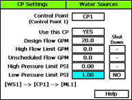
7. Press Next to move to the High Flow Limit GPM field, and then press + or – to enter the maximum amount of flow in gallons per minute.
8. Press Next button to move to the Shut Down field. If you want zones (valves) assigned to this control point’s mainline to be stopped and corresponding MVs shut off when the flow rate exceeds the limit, press + to enter a Y (yes) in the field. If you do not want excessive flow to shut down the system, enter an N (no) in the field.
9. Press Next to move to the Unscheduled Flow Limit GPM field, and then press + or – to enter the maximum amount of unscheduled flow in gallons per minute.
10. Press Next to move to the Shut Down field. If you want the associated MVs to turn off when an unscheduled flow exceeds this limit, press + to enter a Y (yes) in the field. If you do not want excessive flow to shut down the system, enter an N (no) in the field.
11. Press Next to move to the High Pressure Limit PSI field, and then press + or – to enter the maximum amount of pressure in PSI.
12. Press Next to move to the Shut Down field. If you want the associated MVs to turn off when the pressure exceeds this limit, press + to enter a Y (yes) in the field. If you do not want excessive pressure to shut down the system, enter an N (no) in the field.
13. Press Next to move to the Low Pressure Limit PSI field, and then press + or – to enter the minimum amount of pressure in PSI.
14. Press Next to move to the Shut Down field. If you want the associated MVs to turn off when the pressure drops below this limit, press + to enter a Y (yes) in the field. If you do not want low pressure to shut down the system, enter an N (no) in the field.
DeleteStep 6: Set Up and Prioritize Your Water Sources
1. Turn the dial to the Water Sources position.
 2. If the Water Sources Setup option is not highlighted, press Next or Previous to select it.
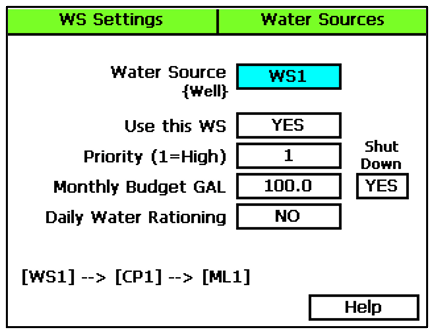
3. Press Enter. The WS Settings screen displays.
4. In the Water Source field, press + or – to designate a number for the water source that you want to set up.
5. Press Next to move to the Use this WS field. Press + or – to toggle the setting between YES and NO as needed.
6. Press Next to move to the Priority field. Press + or – to change the value in the field to a number between 1 and 10 where 1 is the highest priority. When an irrigation system has more than one water source with different priorities, water from the source with the highest priority is used first until the monthly budget limit is reached. Then the system switches to the water source with the next highest priority.
7. Press Next to move to the Monthly Budget GAL field. Press + or – to change the value in the field to show the number of gallons that can be used from this water source during a month. The value increases in increments of 250 gallons.
Note
When the value in the Monthly Budget field is greater than zero, the system monitors the total water used during a single month. If the monthly water used exceeds this number, an alert is generated. If you set the Shut Down field to YES, then the water is stopped until the first of the next month.
8. Press Next to move to the Shut Down field. Press + or – to toggle the value in the field between YES and NO. This setting indicates whether the water source will shut down when the monthly budget amount has been exceeded.
9. Press Next to move to the Daily Water Rationing field. Press + or – to toggle the value in the field between YES and NO. When you enable water rationing, the system determines the daily water ration by dividing the number of gallons in the Monthly Budget field by the number of days in the month. The system will use only the ration amount for daily watering. If a day is skipped, that water ration is available the next day.
DeleteStep 7: Assign Water Sources to the Downstream Hydraulic Components
The BaseStation 3200 supports 8 separate water sources. From the factory, the controller has water source 1 (WS1) enabled and connected to control point 1 (CP1). CP1 is enabled and connected to mainline 1 (ML1). No other water sources are connected or enabled.
Connecting a Water Source to a Control Point
Each water source must be connected to at least one control point.
1. Turn the dial to the Water Sources position.
2. Press Next to select the Assign Water Sources to Control Points option.
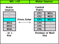
3. Press Enter. The WS CP screen displays.
4. Press + or – to select any available water source in the left column.
5. Press Next or Previous to move to the Control Points column and select an available control point.
6. Press Enter to connect the water source to that control point.
7. Perform one of the following options:
- If you want to connect another water source to a control point, repeat steps 4 – 6.
- If you have finished making changes, turn the dial to the RUN position.
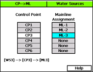
Connecting a Control Point to a Mainline
1. Turn the dial to the Water Sources or Flow position.
2. Press Next or Previous to select the Assign Control Points to Mainlines option.
3. Press Enter. The CP ML screen displays.
4. Press + or – to select any control point in the left column.
5. Press Next or Previous to move to the Mainline Assignment column.
6. Press + or – to select the mainline that you want the control point to be connected to.
7. Perform one of the following options:
- If you want to connect another control point to a mainline, press the Previous button to return to the left column, and then repeat steps 4 – 6.
- If you have finished making changes, turn the dial to the RUN position.
Step 8: Assign Zones to Their Appropriate Mainlines
1. Turn the dial to the Flow position.
2. Press Next or Previous to select the Assign Zones to Mainlines option.
3. Press Enter. The Zones àML screen displays.
4. Press + or – to select any zone in the left column.
5. Press Next to move to the Mainline column.
6. Press + or – to select the mainline that you want the zone to be assigned to. 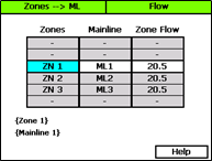
7. Press Next to move to the Zone Flow column.
8. Press + or – to set the value of the GPM flow for this zone.
Perform one of the following options:
- If you want to assign another zone to a mainline, press Previous to return to the left column, and then repeat steps 4 – 8.
- If you have finished making changes, turn the dial to the RUN position.
Step 9: Consider the Mainline Operating Limits
After you have configured your control points, devices, and water source priorities, you need to consider the mainline operating limits to ensure that your irrigation system behaves as expected.
To set up the mainline, turn the dial to the Flow position, and then press Next to highlight the Mainline Setup option.
-
Design Flow GPM – This field is the flow rating for the mainline in gallons per minute (GPM). This flow is likely different from the design flow of the flow device assigned to the control point.
-
Managed by Flow – When you set up the design flow for the mainline and then set this field to YES, the controller will use the design flow of the individual zones (or learned flow) and will turn on zones that are waiting to water until their design flow is equal to or less than the available flow on the mainline.
-
Flow Variance Zone Detect – Flow variance is the actual flow compared to the expected flow. Both above and below expected flow conditions can be detected and then acted upon.
- Flow Variance Shutdown – If you enable the shutdown option for flow variance, the mainline turns off when the flow variance exceeds the limit.