


Each irrigation control valve must be connected to a WeatherTRAK 2-wire Valve Decoder. Each valve decoder is programmed with a station number.
Resource: WeatherTRAK 2-Wire Controller Installation Guide
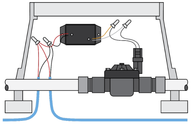
Below are instructions for how to install the Flow Sensor onto the 2-wire path. The ET Pro3 or OptiFlow XR controller also provides a direct-connect option found at the controller terminals.
Wiring a Flow Sensor Decoder
Flow Sensor
1. Power off the two-wire during the installation of any 2-wire device.
2. Install the Flow Sensor decoder as close to the flow device as possible. Follow the flow meter manufacturer’s specifications for required straight pipe before and after the flow meter for accurate readings.
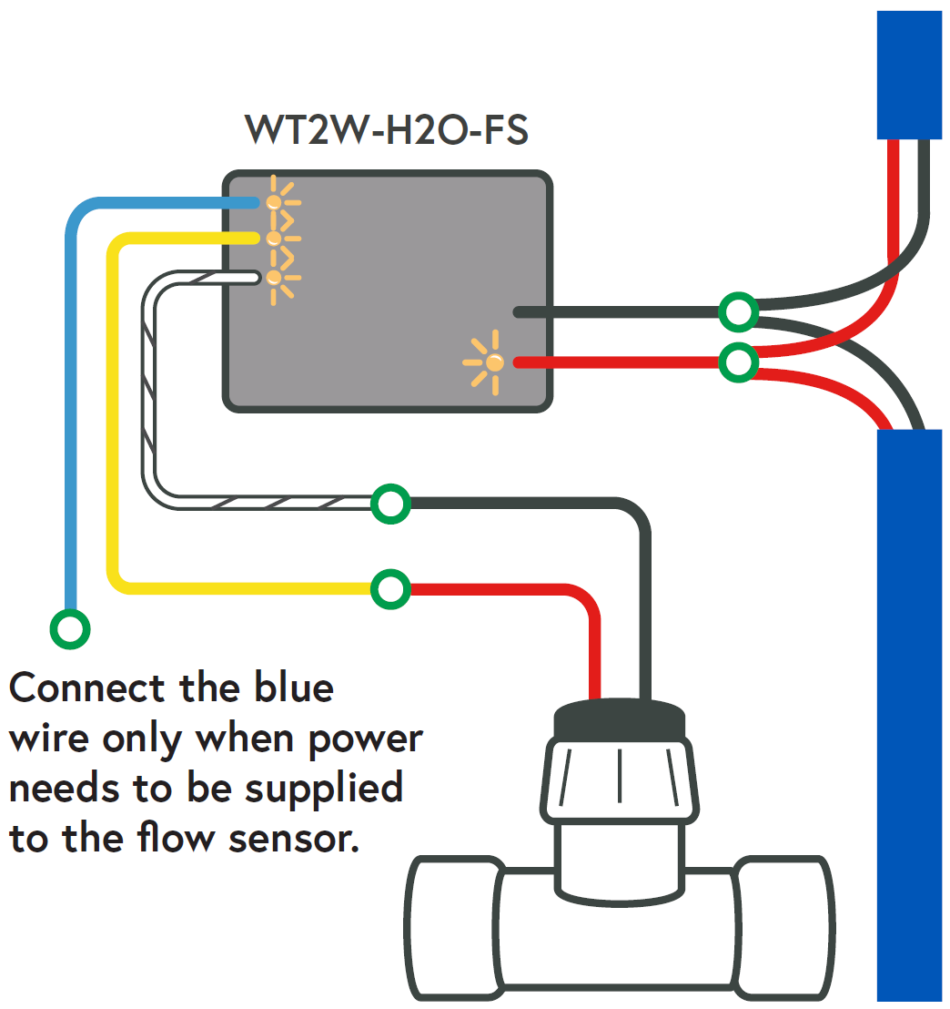
3. Connect the red and black wires from the Flow Sensor decoder to the red and black wires from the 2-wire field. Be sure to maintain polarity by connecting red to red and black to black. Leave 24 to 36 inches of slack on the 2-wire to allow for easy installation and maintenance.
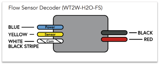
4. Depending on the flow device, connect the black wire to the white wire with black stripe of the decoder. Then connect the red wire from the flow device to the yellow wire from the decoder. The blue wire from the decoder is only to be connected when power needs to be supplied to the flow sensor (like to a Flow3 Hydrometer, for example). Otherwise, cap.
Note: The common wires cannot be shared between different decoders

Flow3 Hydrometer
1. Power off the two-wire during the installation of any 2-wire device.
2. Install the Flow Sensor decoder as close to the flow device as possible. Follow the flow meter manufacturer’s specifications for required straight pipe before and after the flow meter for accurate readings.
3. Connect the red and black wires from the Flow Sensor decoder to the red and black wires from the 2-wire field. Be sure to maintain polarity by connecting red to red and black to black. Leave 24 to 36 inches of slack on the 2-wire to allow for easy installation and maintenance.
4. Connect the bare copper wire (which is the common) from the Flow3 Hydrometer to the white wire with black stripe of the decoder. Then connect the clear wire (which is the sensor wire) from the Flow3 to the yellow wire of the decoder. Lastly, connect the yellow wire (which is the power wire) from the Flow3 to the blue wire from the decoder.
Note: The common wires cannot be shared between different decoders.
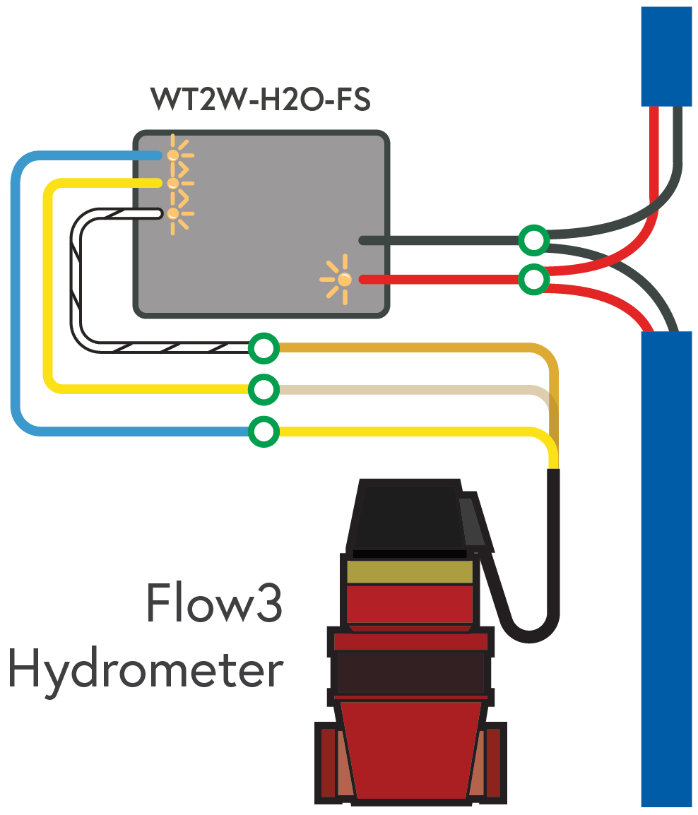

Source: WT2W-H2O-FS Installation Guide
DeleteWiring Diagrams with Flowlink: WT Flow Solutions Installation Guide
H20 2-Wire Decoder: Troubleshooting and Diagnostics Guide